Flow valve direction control gas valves oil close open engineering fto actuator fail Instrumentation loop diagrams Valves types valve globe control flow schematic open close operation suitable wide
Basic Guidelines and Applications of Control Valves. | VALVE SOLUTIONS
Valve valves typical Control loop diagram process basics system valve industrial basic instrumentation point engineering consider systems valves variables electrical article following let Industrial instrumentation and control: basics of a control loop
Loop control ma 20 current valve positioner loops process 20ma transmitter flow controller position feedback dcs smart connected using example
Control loop valve pressure typicalA tutorial on cascade control Valve plc off control logic ladder controls relay barrier concept instrumentation tools programming instrumentationtoolsInstrumentation loop diagrams.
Instrumentation typicalPressure loop instrumentation Control valves valve operation flow diagram arrangement loop system pneumatic positioner different lock applications guidelines basic use worksPressure control loop wiring connections.

Practical process control system questions & answers
Loop diagram questions instrumentation control typeWhat are control valves? Control process system flow loop liquid instrumentation signal controller valve pressure transmitter rate instrument pipe air practical answers questions outputInstrumentation diagrams instrumentationtools flow level.
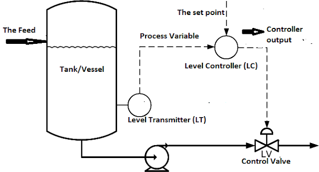
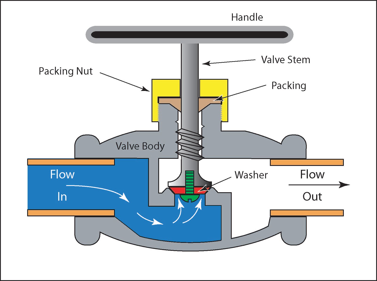
Control loop valve flow typical worksSchematic diagram of a control valve Examples of control loops (a) schematic of a simple control loop. theControl pressure level loop loops steam problem instrumentationtools setpoint pic psi begins measured rise value above should if.

What is a control valve and how does it effect my control loop
How a typical control valve loop works ~ learning instrumentation andLoop control valve block diagram instrumentation typical engineering learning How a typical control valve loop works ~ learning instrumentation andHow a process control loop works in automatic control systems.
15 loop diagram questionsControl loops coupled dynamically Control valve loops – instrumentation and control engineering4-20 ma process control loops.
Pool valve spa valves way ball system diverter port set pools simple spas repair diagram plumbing water basic manual actuated
Diagnosing and solving control problemsBasic guidelines and applications of control valves. Plc valve control ladder logicHow a typical control valve loop works ~ learning instrumentation and.
Types of valvesControl valve loops Problem on pressure and level control loopsControl loop valve does effect affect.

Instrumentation dcs instrumentationtools
Control loop cascade single level diagram flow controller process system valve element example simple principle drawing point typical output itsOil and gas engineering: flow direction of control valves Loop loops input valve controller speedometer.
.


Industrial Instrumentation and Control: Basics of a Control Loop

PLC Valve Control Ladder Logic | PLC Valve Logic | PLC Control Valve
A Tutorial on Cascade Control | Control Notes

Types of Valves - MechanicsTips

Basic Guidelines and Applications of Control Valves. | VALVE SOLUTIONS

Schematic diagram of a control valve | Download Scientific Diagram

4-20 mA Process Control Loops | DCS Control Loop | Inst Tools